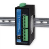
Comnet FDC80TM1 8-Channel Contact Closure Transmitter
Overview
The Comnet FDC80TM1 is an 8-channel supervised contact closure transmitter designed to reliably encode and transmit dry switch and relay contact states over a single multimode optical fiber link. Unlike simple relay circuits that can produce unpredictable output states during transmission loss or power disruption, the FDC80TM1 uses microprocessor-based packet logic: each contact closure is encoded, sequenced, and error-checked before transmission. Garbled or out-of-sequence packets are discarded at the receiver, ensuring the FDC80TM1 never triggers false relay closures—a critical requirement in fire alarm, intrusion detection, and building automation systems where a phantom signal can trigger unnecessary evacuation or false lockdown.
Key Features
- 8 independent supervised channels: Each input supports normally open or normally closed contact configuration, with built-in series and shunt resistors for supervision. You can detect short and open circuit faults on the input side without adding external watchdog circuits.
- Packet-based encoding with error detection: Microprocessor logic orders, encodes, and validates every contact state transition. If a packet arrives corrupted or out of sequence, it is rejected—preventing the random relay closures that plague simple relay repeaters during signal dropout.
- 16 km (10 mile) multimode fiber reach: Operating over a single 62.5/125µm multimode strand with a 16 dB optical power budget, the FDC80TM1 covers campus-scale distances (parking facilities, remote equipment rooms, distributed alarm zones) without requiring a second fiber or active regenerator.
- 25 msec typical response time: Contact closures propagate at 25–35 msec latency, suitable for supervised alarm and control signaling. This speed is adequate for fire and intrusion systems, where sub-second latency is not a regulatory requirement but deterministic behavior is.
- Normally open output relays, 30 VDC @ 1A resistive: The FDC80TM1 paired with its matching receiver drives dry relay contacts rated for 30 VDC and 1A into resistive loads only. This rating is typical for 24 VDC building automation circuits and alarm panel inputs; if your installation uses inductive loads (solenoids, coils), you will need external isolation diodes.
- Summary fault alarm output: A Form C relay in the receiver unit signals any system fault (fiber break, power loss, receiver offline). The fault contact is non-latching and driven by the receiver, so you gain real-time visibility into link health without polling or custom logic.
- Wide operating temperature range, -40 to +75°C: Rated for outdoor equipment cabinets, underground vaults, and non-climate-controlled enclosures. The 3W maximum power draw and low thermal profile mean the transmitter generates negligible heat even in continuous operation.
- 1-rack-slot form factor with hot-swap capability: The FDC80TM1 mounts as a single rack module and is hot-swappable if your rack system supports module insertion under power. Transmitter and receiver are interchangeable between stand-alone tabletop use and Comnet rack frames (sold separately).
- Automatic resettable solid-state current limiters: Internal circuit protection prevents damage from accidental contact short-circuits or transient voltage spikes on input lines. Unlike fused designs, the limiters reset automatically when the fault clears.
- LED status indicators: Power, contact closure state, and summary fault are displayed via front-panel LEDs, enabling visual troubleshooting without test equipment.
Integration and Compatibility
The FDC80TM1 transmitter is part of the Comnet FDC80 series, which includes both multimode (16 km) and single-mode (69 km) variants, and both latching and non-latching receiver configurations. If your fiber link exceeds 16 km, upgrade to the FDC80TS1 (single-mode transmitter) paired with an FDC80RS1 receiver. If your control logic requires relay contacts that remain closed even after power loss or fiber break (latching behavior), pair the FDC80TM1 with an FDC80RM1 latching receiver; for non-latching operation (relays drop when power is lost), use the FDC80NLRM1.
Input and output connections are screw-terminal, compatible with standard 24 VDC building automation wiring. Power is supplied via the same screw terminals (8–15 VDC operating range) or through a separate Comnet C1 rack power distribution system if installed in a rack frame. No special controller or gateway is required—the FDC80TM1 and receiver act as transparent fiber-to-relay converters.
What's in the Box
The FDC80TM1 ships as a single transmitter module. Pairing requires a matching receiver unit (FDC80RM1 or FDC80NLRM1) and multimode optical fiber, which are ordered separately. External series and shunt resistors for contact supervision are included in the package.
Frequently Asked Questions
Q: Does the FDC80TM1 require a matching receiver, or can I use it with any optical receiver?
A: The FDC80TM1 transmitter is proprietary to the Comnet FDC80 series and requires a matching FDC80 receiver (FDC80RM1, FDC80NLRM1, FDC80RS1, or FDC80NLRS1) to decode the packet-encoded contact states. Standard CWDM or DWDM transceivers will not decode the Comnet protocol.
Q: What is the warranty on the FDC80TM1?
A: The FDC80TM1 includes a manufacturer warranty. Refer to the product datasheet or contact the vendor for specific warranty duration and coverage terms.
Q: Can I use single-mode fiber instead of multimode with the FDC80TM1?
A: No. The FDC80TM1 is designed for multimode 62.5/125µm fiber. If you require single-mode fiber (for longer distances or existing infrastructure), order the FDC80TS1 transmitter instead, which carries a 23 dB power budget and supports 69 km links.
Q: What is the typical latency between input contact closure and output relay activation?
A: Response time is 25 msec typical, 35 msec maximum. This includes packet encoding, transmission, and receiver relay settling.
Q: Can I use the FDC80TM1 output relays to switch inductive loads (solenoid valves, motor coils)?
A: The output relay contact rating is 30 VDC, 1A resistive load only. Inductive loads will cause arcing and relay damage unless you add external isolation diodes. For inductive loads, use a separate relay or solid-state switch downstream of the FDC80 output.
Q: Does the FDC80TM1 offer NDAA or TAA compliance?
A: No NDAA or TAA compliance is listed in the product documentation. Verify with the vendor if government procurement restrictions apply to your project.
I spec the Comnet FDC80TM1 when a facility needs to transmit dry contact states—alarm zones, equipment status, door locks—over campus distances without the risk of phantom relay closures. The microprocessor-based packet encoding and error detection are what set this apart from cheap fiber-to-relay converters. If a transmission gets corrupted, the FDC80TM1 simply discards it instead of triggering a false alarm.
Technical Highlights:
- 25 msec typical response time with packet validation: Contact closures propagate at 25–35 msec latency, and every packet is sequenced and error-checked before the receiver relay activates. You lose a few milliseconds to the microprocessor logic, but you gain immunity to random false signals—worth the tradeoff in any supervised alarm or access control network.
- 16 km multimode fiber reach on a single 16 dB power budget: Cover parking facilities, remote substations, or distributed equipment rooms on one fiber strand. If you're already running multimode infrastructure, the FDC80TM1 plugs in without additional regeneration or active components.
- Summary fault alarm output (Form C relay, non-latching): The receiver drives a dry relay contact on any system fault. Real-time fault signaling means your building automation system or security panel knows immediately if the fiber link goes down or the transmitter loses power. No polling, no guessing.
- 8 supervised input channels with short/open detection: Built-in series and shunt resistors on each input allow the transmitter to sense an open (broken wire) or short (shorted contact) condition without external supervision modules. Reduces wiring complexity in distributed alarm zones.
Deployment Considerations:
- Output relay rating is 30 VDC, 1A resistive load only—no inductive loads without external isolation diodes. If your downstream circuits include solenoid coils or relay coils, budget for external flyback diodes on each contact output.
- The FDC80TM1 is the multimode variant (16 km max). Campus links longer than 16 km require the FDC80TS1 (single-mode, 69 km reach). Plan your fiber infrastructure and choose the transmitter accordingly—mixing multimode and single-mode transceivers on the same link will not work.
- Power supply must deliver 8–15 VDC at 3W maximum. If you're powering from a panel backup battery during mains failure, confirm the battery voltage stays within this range under load. Undervoltage will cause packet loss.
Deploy the FDC80TM1 when you're transmitting supervised alarm or access control contact states over fiber to a remote building or cabinet where deterministic, error-free signal integrity is non-negotiable—fire alarm systems, intrusion detection networks, or distributed door unlock sequences. The packet-based architecture eliminates the guesswork of simple relay repeaters.