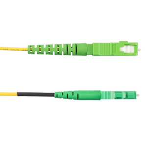
Panduit F92ERANB1SNM015 Opti-Core OS2 Single-Mode Fiber Patch Cord
The Panduit F92ERANB1SNM015 is a 15-meter (49.2 ft) OS2 single-mode fiber optic patch cord built for long-haul datacenter and campus backbone interconnects. This duplex 2-fiber jumper terminates SC/APC on one end and LC/APC on the other, delivering the low back-reflection performance APC (angled physical contact) connectors are known for—critical when you're running 10G, 40G, or 100G optical transceivers sensitive to return loss. The 1.6 mm cable diameter keeps density manageable in crowded patch panels and breakout applications, while the OFNR (vertical riser) flammability rating clears NEC Article 770 for in-building vertical pathways without requiring plenum-rated cable in non-plenum spaces. Standard polarity and factory-terminated connectors mean you pull it from the bag, verify end-face cleanliness, and plug it in—no field termination, no guesswork on fiber alignment.
Key Features
- OS2 9/125 μm single-mode fiber—supports transmission distances up to 10 km (10GBASE-LR) or 40 km (10GBASE-ER) depending on transceiver, far exceeding multimode range limits
- SC/APC to LC/APC connectors with 8° angled end-faces—back reflection typically below -60 dB, preventing signal degradation in high-bitrate coherent and analog optical systems
- 1.6 mm duplex cable—half the diameter of standard 3.0 mm cordage, reducing pathway fill and improving airflow in high-density racks
- OFNR vertical riser rating (UL 1666)—approved for installation in vertical shafts and floor-to-floor risers per NEC 770.113(B), avoiding the cost premium of plenum cable where not required
- 15-meter length—ideal for cross-connect between distribution frames in the same equipment room or short building-to-building spans in a campus fiber ring
- Yellow jacket—industry-standard color-coding for single-mode OS2 fiber, preventing accidental cross-connection with OM3/OM4 multimode (aqua) or OM5 (lime green) plant
- Factory-terminated and tested—ships with protective dust caps and insertion-loss certification, eliminating the labor and yield risk of field termination
- Panduit Opti-Core heritage—engineered to the same mechanical and optical specs as Panduit's premise fiber systems, ensuring consistent performance across your structured cabling install
Single-Mode OS2 for Long-Reach Applications
OS2 fiber uses a 9 μm core diameter—roughly one-tenth the size of the 50 μm or 62.5 μm cores in multimode fiber. This tight core supports only a single propagation mode, eliminating modal dispersion and enabling transmission over kilometers rather than hundreds of meters. In a typical datacenter or enterprise network, you'll deploy OS2 jumpers like the F92ERANB1SNM015 whenever the link budget calls for distances beyond 300–550 meters (the practical ceiling for OM3/OM4 multimode at 10G), or when you're future-proofing for 40GBASE-LR4, 100GBASE-LR4, or coherent optics that demand the chromatic-dispersion headroom only single-mode provides. The 15-meter length of this cord fits the sweet spot for intra-building backbone links—connecting a telecommunications room on the third floor to the main distribution frame on the ground floor, or bridging two racks in a large colocation cage where copper DAC or multimode OM4 would fall short on reach or upgrade path.
Panduit's OS2 cordage meets or exceeds the ITU-T G.652.D specification, which defines maximum attenuation (≤0.4 dB/km at 1310 nm, ≤0.3 dB/km at 1550 nm) and zero-dispersion wavelength range. In practice, this means a 15-meter jumper contributes roughly 0.006 dB of fiber attenuation at 1310 nm—negligible compared to connector insertion loss—but the real value is in the dispersion spec: G.652.D fiber supports dense wavelength-division multiplexing (DWDM) across the C-band (1530–1565 nm) without the water-peak attenuation spike that plagued older G.652.A fiber. If your roadmap includes lambda services from a carrier or multi-wavelength optics for capacity scaling, OS2 is the only premise fiber that won't force a rip-and-replace when you light up those channels.
APC Connectors: Why the Angle Matters
The "APC" designation on both the SC and LC connectors stands for angled physical contact—the fiber end-face is polished at an 8° angle relative to the connector ferrule axis, rather than the 0° perpendicular polish of a standard UPC (ultra physical contact) connector. When light exits an APC connector, any Fresnel reflection at the glass-air interface is redirected into the cladding rather than back down the core, resulting in return loss below -60 dB (often -65 dB or better). UPC connectors, by contrast, typically achieve -50 dB return loss, which is adequate for LED-based multimode systems but marginal for laser-driven single-mode links—especially coherent transceivers, RF-over-fiber, and analog CATV distribution, where back-reflection can cause bit errors, phase noise, or composite second-order (CSO) distortion.
The trade-off is that APC connectors must mate only with other APC connectors; mixing APC and UPC creates an air gap and high insertion loss because the angled and flat end-faces don't align. Panduit color-codes APC connectors with green boots (you'll see this on the SC and LC ends of the F92ERANB1SNM015), while UPC connectors use blue boots, preventing accidental cross-connection during install or moves-adds-changes. In a datacenter backbone or storage-area-network (SAN) deployment, you'll typically standardize on APC for all single-mode jumpers to maximize margin and avoid the "which connector type is this?" question six months later when a tech is troubleshooting a link in low light.
SC/APC to LC/APC Connector Pair
This jumper uses an SC connector on one end and an LC connector on the other—an asymmetric pairing common in backbone-to-access transitions. The SC connector (Subscriber Connector, also called "square connector" for its cross-section) is a push-pull single-ferrule design that's been the workhorse of premise fiber since the 1990s; you'll find SC jacks on legacy Cisco switches, older fiber panels, and backbone cassettes that predate the LC small-form-factor (SFF) migration. The LC connector (Lucent Connector, sometimes "little connector") uses a 1.25 mm ferrule—half the diameter of the SC's 2.5 mm ferrule—and a modular-jack form factor that fits twice the port density in the same rack space. Modern 10G/25G/100G transceivers (SFP+, SFP28, QSFP28) almost universally use LC or the even-smaller MDC interface, so an SC-to-LC jumper bridges the gap when you're connecting a new switch with LC ports to an older fiber distribution panel or backbone trunk that terminates in SC.
Both connectors on the F92ERANB1SNM015 are duplex—the SC end is a paired SC/APC duplex connector (often called an "SC duplex clip"), and the LC end is a duplex LC/APC connector, so you get transmit and receive fibers in a single plug. The jumper follows standard polarity (TIA-568-C.3 Method A), meaning if you plug the SC end into a backbone panel's duplex SC jack and the LC end into a switch's duplex LC transceiver, transmit on one end lines up with receive on the other without requiring a crossover or polarity-flip adapter. This is critical for plug-and-play operation—non-standard polarity jumpers (Method B or Method C) exist for specific trunk-to-cassette architectures, but they're labeled and bagged separately to avoid the "link won't come up" service calls that happen when you mix polarity schemes.
1.6 mm Cable for High-Density Routing
Traditional duplex fiber jumpers use a 2.0 mm or 3.0 mm zipcord construction—two individual 900 μm tight-buffered fibers inside a common jacket. The F92ERANB1SNM015 steps down to 1.6 mm overall diameter by using thinner buffer layers and a more compact jacket, cutting the cross-sectional area nearly in half compared to 3.0 mm cordage. In a 1U fiber patch panel with 24 or 48 LC duplex ports, that diameter reduction translates directly to bend-radius relief and pathway congestion relief: you can route a full panel's worth of 1.6 mm jumpers through a 2-inch horizontal cable manager without the spaghetti-bundle effect that forces you to overbend cables or leave the manager door open. The smaller diameter also improves airflow in the back of the rack—less cable volume blocking the hot-aisle exhaust means lower intake temperatures for the switches and routers one rack over.
The trade-off is slightly lower crush resistance and pull tension compared to 3.0 mm cordage—Panduit rates this jumper for a 100 N (22.5 lbf) short-term tensile load and a 12.5 mm minimum bend radius during installation (25 mm long-term), versus 15 mm / 30 mm for heavier-jacket designs. In practice, those limits are well above the stress a jumper sees in a patch-panel-to-switch connection, but if you're pulling cable through conduit or tie-wrapping bundles with a tensioning tool, you'll want to set the tool's break-away clutch to the lower rating and avoid sharp-radius hooks. The OFNR flammability rating is independent of cable diameter—this jumper passes the UL 1666 riser flame test (the same vertical tray test that qualifies Category 6A riser cable), so you can run it in the same pathways as your copper premise plant without mixing plenum and non-plenum cable types.
OFNR Vertical Riser Rating for In-Building Distribution
The National Electrical Code (NEC) Article 770 divides optical fiber cables into four main flammability categories: OFNP (plenum), OFNR (riser), OFNG (general purpose), and OFN (basic). OFNR cable is designed to pass the UL 1666 vertical flame test, which simulates a fire in a multi-story vertical shaft—the test measures how far flame propagates up a 4.8-meter cable sample in a controlled airflow. Cable that self-extinguishes and limits char length qualifies as riser-rated, meeting the NEC 770.113(B) requirement for installation in "vertical runs in a shaft" or between floors without requiring a fireproof enclosure. This makes OFNR the default choice for intra-building backbone fiber: you can run the F92ERANB1SNM015 from a ground-floor MDF up a riser conduit to a third-floor IDF without the cost and stiffness penalty of plenum-rated (OFNP) cable, as long as the pathway doesn't pass through an air-handling plenum space.
If your building's backbone conduit does route through a plenum ceiling or raised floor that's part of the HVAC return-air path, NEC 770.113(A) requires OFNP cable instead—plenum cable uses low-smoke, low-flame-spread jacket materials (typically fluorinated ethylene propylene, FEP, or perfluoroalkoxy, PFA) that cost 30–50% more than the PVC or low-smoke zero-halogen (LSZH) jackets on riser cable. The good news is that most equipment-room-to-equipment-room jumpers don't enter plenum spaces—the typical install is a sealed riser conduit or cable tray outside the HVAC envelope—so OFNR hits the regulatory requirement without the materials premium. In a data-center row or telecommunications room, you'll use OFNR jumpers like the F92ERANB1SNM015 for vertical patch-panel-to-patch-panel links and horizontal rack-to-rack spans, reserving OFNP for the few runs that cross plenum zones.
Yellow Jacket: Industry-Standard Color Code for OS2
TIA-598-D and ISO/IEC 11801 define a color-coding scheme for optical fiber cable jackets to prevent accidental cross-connection between incompatible fiber types. Single-mode OS2 fiber uses a yellow jacket; multimode OM1/OM2 (62.5/50 μm) uses orange; OM3 (laser-optimized 50 μm) uses aqua; OM4 (higher-bandwidth 50 μm) also uses aqua (sometimes with an OM4 print legend); and OM5 (wideband multimode for short-wave WDM) uses lime green. The F92ERANB1SNM015's yellow outer jacket immediately identifies it as single-mode, so a technician installing a 10GBASE-LR transceiver knows at a glance that this is the correct jumper—plugging a multimode OM3 jumper into a single-mode transceiver will link up but cut the distance spec from 10 km down to 300 meters (or cause a complete link failure if the transceiver's laser is outside the OM3 bandwidth window).
Connector boots on the SC and LC ends are green, which is the universal APC indicator (UPC connectors use blue boots). Between the yellow jacket and green boots, you have two visual cues that this is a single-mode APC jumper, reducing the odds of the classic install mistake where a tech grabs an SC-UPC-to-LC-UPC blue-booted jumper from the spares bin and wonders why the link has 3 dB of excess loss and intermittent errors. In a large datacenter or campus network, consistent color-coding across all jumpers, trunks, and cassettes is the first line of defense against the "everything looks like yellow spaghetti under the floor" problem—Panduit's Opti-Core product line follows TIA-598-D by default, so you're building on a standard rather than a vendor-specific scheme.
Factory Termination and Insertion-Loss Testing
Panduit factory-terminates the SC and LC connectors on the F92ERANB1SNM015 using automated polishing and epoxy-cure processes, then tests each jumper for insertion loss and return loss before it leaves the plant. You'll find a test report or compliance label in the bag (depending on packaging) certifying that the jumper meets the TIA-568-C.3 insertion-loss limit (≤0.75 dB for a single-mode connector pair) and the -60 dB return-loss spec for APC connectors. Field termination of single-mode connectors is possible with fusion splicers or mechanical-splice kits, but it's a 15–20 minute process per connector that requires cleaving the fiber to a mirror finish, aligning the ferrule under a microscope, and curing epoxy under controlled temperature—any contamination or misalignment adds loss, and APC end-face geometry is especially sensitive to polish angle. Factory jumpers eliminate that labor and yield risk: you're paying for the termination once at volume pricing rather than paying a tech's hourly rate to terminate on-site and re-do connectors that fail inspection.
The insertion-loss spec is particularly important for link-budget planning. A typical 10GBASE-LR transceiver has an optical power budget around 7–8 dB, which must cover fiber attenuation (15 m × 0.4 dB/km ≈ 0.006 dB, negligible), connector insertion loss (0.75 dB per connector pair, so two jumpers plus a mating adapter = 1.5 dB worst case), splice loss if any (0.1–0.3 dB per fusion splice), and a system margin of 2–3 dB to account for aging and repair splices. A factory jumper with certified ≤0.75 dB insertion loss lets you design to the TIA spec rather than guessing at field-terminated performance, and it gives you a known-good reference for troubleshooting—if a link is down, you can swap in a factory jumper and immediately rule out (or confirm) connector contamination or damage as the root cause.
Application Fit: Datacenter Backbone, Campus Fiber Rings, and SAN Interconnects
The F92ERANB1SNM015's 15-meter length and SC-to-LC connector pairing make it a natural fit for three common deployment scenarios. First, intra-building backbone links: in a multi-story office or light-industrial building, you'll run a 12-fiber or 24-fiber OS2 trunk from the ground-floor MDF up the riser to each floor's IDF, terminate the trunk on SC duplex panels, then use SC-to-LC jumpers like this one to patch from the backbone panel to the LC ports on the floor switch. The 15-meter length covers the typical IDF equipment-room depth (3–5 meters from panel to switch) plus the vertical rise between floors (3–4 meters per floor) with enough slack for service loops and cable management. Second, campus fiber rings: in a university or corporate campus with multiple buildings, you might run a fiber trunk from the central data center to a remote building's telecom room, terminate it on an SC panel, and patch to LC-equipped edge switches—the SC-to-LC asymmetry lets you standardize on SC for all backbone infrastructure while using LC for all active equipment. Third, storage-area-network (SAN) interconnects: Fibre Channel switches and directors often use LC SFP+ or SFP28 transceivers for 16G/32G FC links, but the SAN core might uplink to a 10G Ethernet backbone via SC-terminated fiber—this jumper bridges that gap without requiring LC-to-SC adapter blocks that add insertion loss and failure points.
The OFNR rating expands installation options compared to general-purpose (OFNG) cable, which is restricted to horizontal runs and can't legally be installed in vertical shafts or between floors per NEC 770.113. If you're retrofitting fiber into an existing building, the difference between OFNR and OFNG often determines whether you can reuse the existing riser conduit or whether you need to pull new plenum-rated cable at 2–3× the material cost. The 1.6 mm diameter is a secondary win in retrofit scenarios—older 4-inch riser conduits are often packed with legacy Cat5e and coax, leaving limited room for new cable; a bundle of 1.6 mm fiber jumpers threads through tighter spaces than 3.0 mm cordage, sometimes avoiding the need to abandon old cable or install a parallel conduit.
15 meters is short enough that chromatic dispersion and polarization-mode dispersion (PMD) are non-issues even at 100G data rates—those impairments become link-budget factors at multi-kilometer distances, but over 15 m the accumulated dispersion is measured in femtoseconds, well below the symbol period of any commercial transceiver. The practical distance ceiling for this jumper is set by your transceiver's power budget and the number of connector pairs in the link, not by the fiber itself. If you're designing a link longer than 15 m, you can series-connect multiple jumpers via SC or LC duplex mating adapters (each adapter adds one connector pair and roughly 0.5–0.75 dB insertion loss), but best practice is to order a single longer jumper to minimize loss and failure points—Panduit's Opti-Core line is available in lengths from 1 m to 300 m in 1-meter increments for custom link distances.
Installation and Maintenance Notes
Before mating the F92ERANB1SNM015, inspect both connector end-faces under a fiber microscope or inspection scope—contamination (dust, skin oils, cleaning-solvent residue) is the leading cause of high insertion loss and intermittent link errors in fiber systems. Even a 5-micron dust particle on a 9-micron core can block 50% of the optical signal. Panduit ships this jumper with dust caps on both ends; leave the caps on until you're ready to plug in, and if you see any debris on the end-face, clean with a one-click cleaner (a mechanical push-to-clean tool with a dry ribbon) or lint-free wipes and isopropyl alcohol (IPA). APC end-faces are more sensitive to contamination than UPC because the angled polish creates a smaller contact area—if you touch the ferrule with your finger, the skin oils will bake onto the glass under the contact pressure and cause permanent insertion-loss degradation that can't be cleaned without re-polishing the connector (which is not field-serviceable).
Observe the 12.5 mm minimum bend radius during installation and 25 mm long-term. Single-mode fiber is less tolerant of tight bends than multimode because the smaller core diameter means light escapes into the cladding (macro-bend loss) at larger bend radii—a 10 mm radius bend in OS2 fiber can add several dB of loss at 1550 nm, enough to drop a 10G link. If you're routing this jumper through a horizontal cable manager or around a tight corner in a ladder rack, use rounded guide fingers or bend-radius sleeves to enforce the 25 mm minimum. The 1.6 mm cable diameter helps here—thinner cable naturally bends to a larger radius under its own stiffness, reducing the risk that a loose service loop will kink below the bend-radius limit.
The OFNR jacket is PVC or LSZH depending on manufacturing batch (check the print legend on the cable); both pass the UL 1666 riser test, but LSZH produces less smoke and no halogen acid gases if it burns, which is preferred in enclosed spaces or areas with sensitive electronics. If your facility has a low-smoke materials policy (common in datacenters and healthcare), verify the jacket material on the reel or bag label. Panduit's LSZH jumpers are typically marked "LSZH" or "LS0H" in the print legend and use a gray or yellow jacket with a matte finish, while PVC jumpers have a glossy yellow jacket. Functionally the two are identical for non-fire scenarios—the OFNR rating guarantees the same vertical flame performance regardless of jacket chemistry.